
Introduction
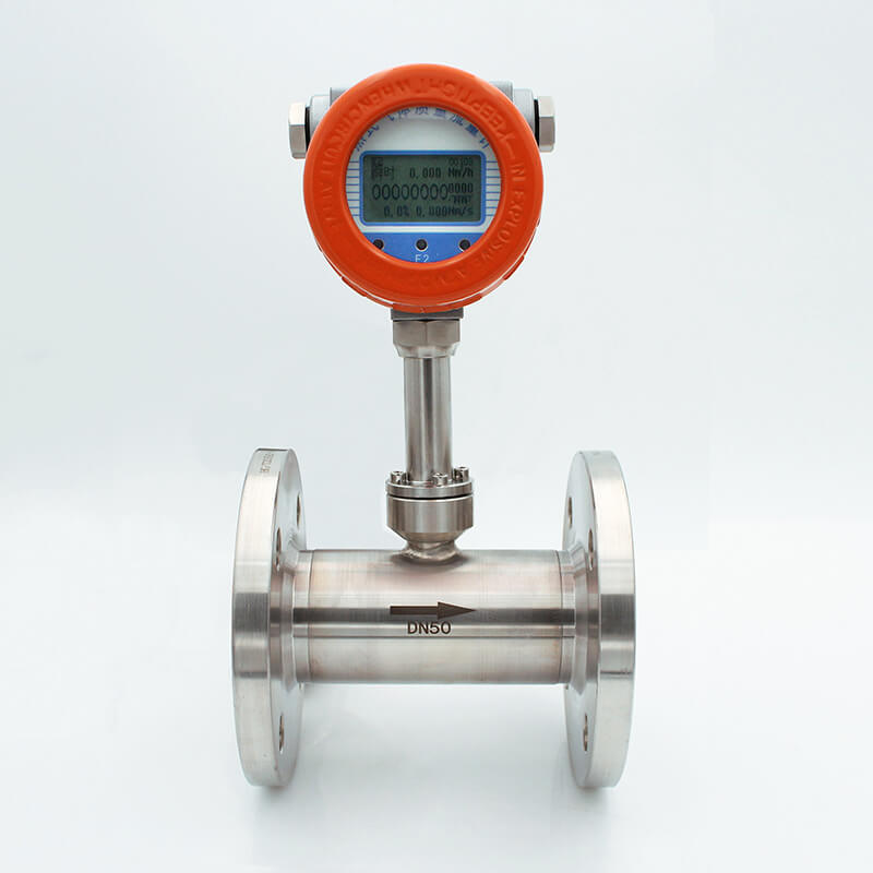
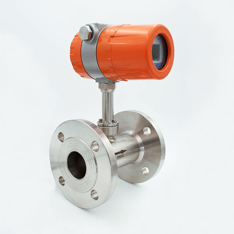
The flange type thermal flow meter is a flow meter designed based on the principle of heat diffusion. That is, when the fluid flows through the heated object, the heat dissipated by the heated object is in a certain proportional relationship with the flow rate of the fluid. The sensor of this series of flow meters has two standard-grade RTDs, one for the heat source and the other for measuring the fluid temperature. When the fluid flows, the temperature difference between the two is linearly related to the flow rate. This relationship is then converted into a linear output of the flow measurement signal through microelectronic control technology.
Flange thermal gas mass flow meter advantanges :
●Adopt platinum resistance sensor with stable performance;
●Not high requirements for straight pipe section, 1-2D;
●Not sensitive to fine particles such as dust;
●Not related to medium temperature and pressure;
●Online continuous flow loading and unloading, easy maintenance;
●Online dynamic correction current/voltage output;
●No moving parts, vibration influence can be ignored;
●Adopt high humidity algorithm to achieve high-precision measurement;
●Proprietary high temperature algorithm, medium temperature can reach +510℃;
●Range ratio is 1000:1, which can be expanded according to user requirements;
●Proprietary algorithm can achieve high linearity, high repeatability and high precision;
●12-point dynamic correction of flow signal, built-in 10-point correction;
●Adopt proprietary technology "balanced structure packaging", medium temperature self-compensation;
●Can realize large-caliber small flow measurement, the minimum flow can be measured to zero, with a resolution of 0.001m/s;
●Adopt RS-485 communication, or HART communication, MODBUS protocol, etc. to realize factory automation and integration.
Application
Flange thermal gas mass flow meter application:
Thermal gas air flow meters are widely used in the oil and gas industry, power industry, chemical industry, metallurgical industry, pulp and paper industry, food and pharmaceutical industry, environmental protection, glass, ceramics and building materials industry, etc.
Mainly used to measure dry gases such as air, natural gas, liquefied petroleum gas and biogas. However, thermal gas mass flow meters cannot be used to measure steam, moisture and acetylene. Specific applications include: oxygen, nitrogen, hydrogen, chlorine and multi-component gas measurement; blast furnace gas, coke oven gas measurement; flue gas measurement; aeration and chlorine measurement in biogas and water treatment; compressed air measurement; natural gas, liquefied gas, flare gas and other gas flow measurement; primary and secondary air flow measurement of blast furnaces in power plants; flow measurement of mine ventilation or exhaust systems; air flow measurement in gas combustion processes; chimney flue gas flow (velocity) measurement (CEMS); decomposition furnace flue gas flow measurement; gas flow measurement in cement, cigarette and glass factory production processes; gas flow measurement in solvent recovery systems; gas flow measurement in semiconductor chip manufacturing processes; carbon dioxide gas flow measurement in beer production processes; gas flow (velocity) measurement in heating, ventilation and air conditioning systems; gas flow measurement in coal-fired boilers; real-time flow (velocity) detection in mine ventilation or exhaust systems.
Application areas:
1. Public works - power, gas and water treatment monitoring
Pipeline gas; general system; biogas; coal gas; natural gas; liquefied gas; boiler preheating air
2. Oil and gas industry
Energy exchange; well filling gas recovery; gas metering; gas quality analysis; gas leak test; natural gas measurement; flare gas monitoring.
3. Power industry
Gas measurement in the gas distribution process of the fuel system; measurement of various gases in boilers and auxiliary systems; gas measurement in gas furnaces; hydrogen measurement; primary and secondary air measurement in blast furnaces of power plants.
4. Chemical industry
Flue gas circulation monitoring; gas flow measurement in sampling systems; gas flow measurement of induced draft fans; ammonia measurement in fertilizer plants; various gas flow measurements in battery plants.
5. Metallurgical industry
Gas filling measurement in steel plants; blast furnace gas measurement in steel plants; coke oven gas measurement in coking plants; measurement and control of rolling mill heating furnace gas (blast furnace gas, coke oven gas, natural gas, etc.); control of hydrogen, oxygen, nitrogen and other gases in heat treatment quenching furnaces, etc.
6. Pulp and paper industry
Gas measurement in wastewater treatment systems; flue gas flow monitoring; boiler secondary/tertiary air recovery; boiler gas and air supply measurement.
7. Food and pharmaceutical industry
Fresh air addition during processing; carbon dioxide treatment in breweries; hot air flow in bottle sterilizers; gas flow measurement during thermal oxidation; ventilation systems; boiler air intake, exhaust and process control.
8. Environmental protection
Gas measurement in biogas utilization; chlorine measurement in chlorine treatment; gas measurement in aeration tanks during sewage treatment; sulfur dioxide and nitrogen oxide emission monitoring in chimney flue gas.
9. Other industries
Compressed air measurement in factories; Powder-gas ratio control during coal combustion; Vertical mill hot air flow control in cement industry.
| Measuring Medium | Various of Gas (Except acetylene) |
| Pipe Size | (Insert connection) DN50-DN2000mm ,In-line connection(DN10-DN2000mm) |
| Velocity | 0.1-100Nm/s |
| Accuracy | ±1% |
| Working Temperature | Sensor:-40~+220 degC Transmitter:-20~+45 degC |
| Working Pressure |
Insertion Sensor:medium pressure ≤1.6Mpa Flanged Sensor:medium pressure ≤4.0Mpa Special pressure please double check |
| Power Supply |
Compact type: 24VDC or 220VAC, Power consumption ≤18W Remote type:220VAC,Power consumption ≤19W |
| Response Time | 1s |
| Output | 4-20mA(optoelectronic isolation,maximum load 500Ω),Pulse RS485(optoelectronic isolation) and HART |
| Alarm Output | 1-2 line Relay, Normally Open state, 10A/220V/AC or 5A/30V/DC |
| Sensor Type | Standard Insertion, Hot-tapped Insertion and Flanged |
| Construction | Compact and Remote |
| Pipe Material | Carbon Steel, Stainless Steel,Plastic etc. |
| Display | 4 lines LCD Mass flow, Volume flow in standard condition, Flow totalizer, Date and Time, Working time, and Velocity, etc. |
| Protection |
IP65 |
Flange Thermal Gas Mass Flow Meter Sizing
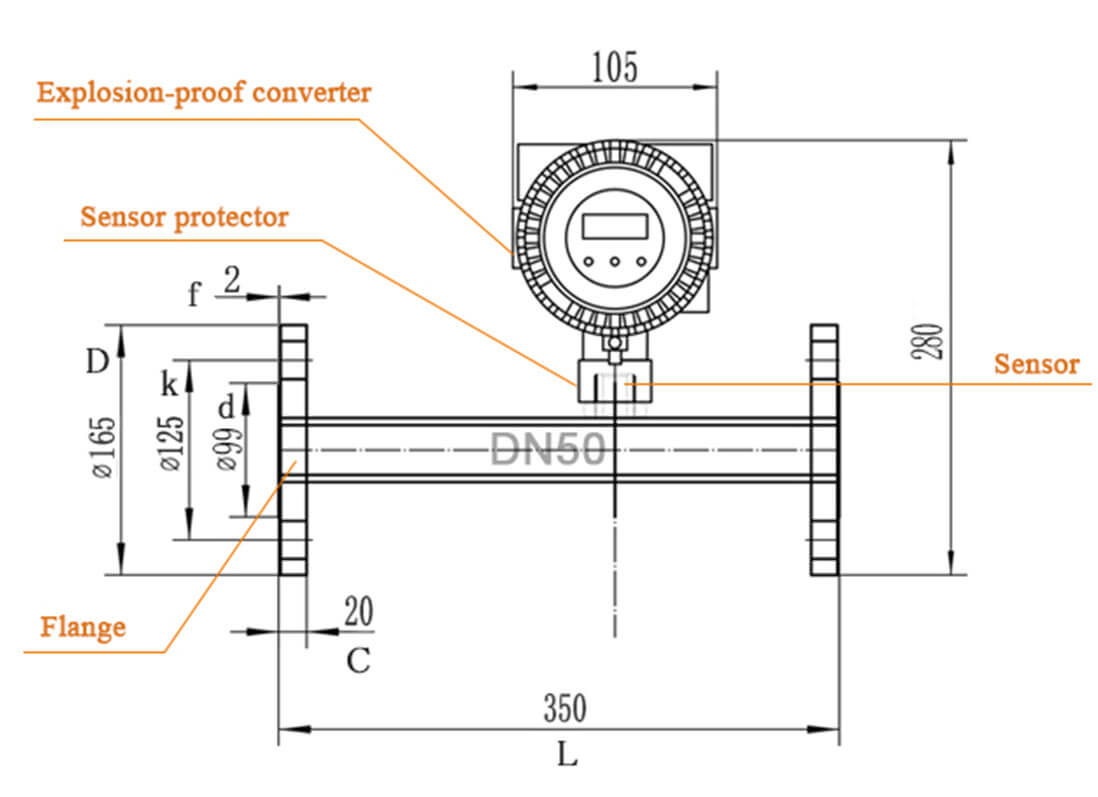

| Nominal Diameter | Flange outer diameter | Center hole | Bolt hole | Screw Threads | Sealing face | Flange thickness | Installation length | |
| DN | D | k | n x L | d | f | C | L | |
| 15 | 95 | 65 | 4x14 | M12 | 46 | 2 | 14 | 280 |
| 20 | 105 | 75 | 4x14 | M12 | 56 | 2 | 16 | 280 |
| 25 | 115 | 85 | 4x14 | M12 | 65 | 2 | 16 | 280 |
| 32 | 140 | 100 | 4x18 | M16 | 76 | 2 | 18 | 350 |
| 40 | 150 | 110 | 4x18 | M16 | 84 | 2 | 18 | 350 |
| 50 | 165 | 125 | 4x18 | M16 | 99 | 2 | 20 | 350 |
| 65 | 185 | 145 | 4x18 | M16 | 118 | 2 | 20 | 400 |
| 80 | 200 | 160 | 8x18 | M16 | 132 | 2 | 20 | 400 |
| 100 | 220 | 180 | 8x18 | M16 | 156 | 2 | 22 | 500 |
| ( mm ) |
Air |
Nitrogen ( N2 ) |
Oxygen ( O2 ) |
Hydrogen ( H2 ) |
| 15 | 65 | 65 | 32 | 10 |
| 25 | 175 | 175 | 89 | 28 |
| 32 | 290 | 290 | 144 | 45 |
| 40 | 450 | 450 | 226 | 70 |
| 50 | 700 | 700 | 352 | 110 |
| 65 | 1200 | 1200 | 600 | 185 |
| 80 | 1800 | 1800 | 900 | 280 |
| 100 | 2800 | 2800 | 1420 | 470 |
| 125 | 4400 | 4400 | 2210 | 700 |
| 150 | 6300 | 6300 | 3200 | 940 |
| 200 | 10000 | 10000 | 5650 | 1880 |
| 250 | 17000 | 17000 | 8830 | 2820 |
| 300 | 25000 | 25000 | 12720 | 4060 |
| 350 | 45000 | 45000 | 22608 | 5600 |
| 400 | 70000 | 70000 | 35325 | 7200 |
| 450 | 100000 | 100000 | 50638 | 9200 |
| 500 | 135000 | 135000 | 69240 | 11280 |
| 600 | 180000 | 180000 | 90432 | 16300 |
| 700 | 220000 | 220000 | 114500 | 22100 |
| 800 | 280000 | 280000 | 141300 | 29000 |
| 900 | 400000 | 400000 | 203480 | 36500 |
| 1000 | 600000 | 600000 | 318000 | 45000 |
| 2000 | 700000 | 700000 | 565200 | 18500 |
|
Model
|
QTMF
|
X | X | X | X | X | X | X |
|
Caliber
|
DN10-DN4000 (3/8"-158")
|
|||||||
|
Structure
|
Compact
|
C | ||||||
|
Remote
|
R | |||||||
|
Explosion Proof
|
Ex d IIC T6 Gb
|
EX | ||||||
|
Without
|
W | |||||||
|
Material
|
SS304
|
304 | ||||||
|
SS316
|
316 | |||||||
|
others
|
O | |||||||
|
Connection
|
Flange
(DN10~DN300mm)
|
PN10/PN16/PN25/PN40(DIN)
|
D** | |||||
|
A15:150#, A30:300# (ANSI)
|
A** | |||||||
|
10K/20K/30K/40K (JIS)
|
J** | |||||||
| Tri-clamp (DN10~DN100mm) | C | |||||||
| Thread (DN10~DN100mm) | T | |||||||
| Insertion (DN32~DN4000mm) | I | |||||||
|
Power Supply
|
AC85~250V
|
AC | ||||||
|
DC24~36V
|
DC | |||||||
|
Signal Output
|
4-20mA+Pulse+RS485
|
RS | ||||||
|
4-20mA+Pulse+HART
|
HT | |||||||
Installation
Flange-type thermal gas mass flowmeter installation:
1. In terms of installation posture, most thermal distributed mass flowmeters can be installed in any posture (horizontal, vertical or inclined), as long as the electrical zero point adjustment is performed at the working pressure and temperature after installation. However, some instruments are sensitive to the installation posture and must be operated strictly in accordance with the instructions. The thermal mass flowmeter has a long response time and is not suitable for pulsating flow. It is prohibited to be exposed to an environment containing a large amount of corrosive gases. The vibration of the pipe connecting the thermal mass flowmeter within the commonly used range will not cause vibration interference. The maximum allowable ambient temperature and medium temperature range must be observed. Avoid condensation (such as installing condensation traps, insulation materials, etc.), install the transmitter in a cool place or use a sunshade. It is prohibited to share power with machines such as frequency converters and electric welders that may cause power line interference.
Daily maintenance of flanged thermal gas mass flowmeter:
In the daily operation of thermal gas mass flowmeter, the flowmeter should be regularly inspected and cleaned, loose parts should be tightened, and abnormal conditions in the flowmeter operation should be discovered and handled in time to ensure the normal operation of the flowmeter, reduce and delay the wear of parts, and extend the service life of the flowmeter. Some flowmeters will scale after a period of use, and must be cleaned by acid cleaning or other methods according to the degree of scaling.