

Introduction
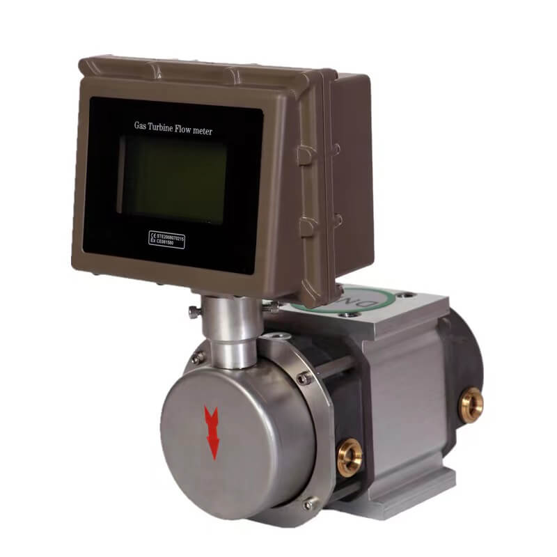
Gas rotor flowmeter, also known as Roots flowmeter, is a high-precision instrument mainly used for continuous or intermittent measurement of gas or liquid flow in pipelines. It has the characteristics of high measurement accuracy, good reliability, low working noise, wide range, small size, light weight, easy installation and maintenance, reliable use and long life. It is widely used in the flow measurement of natural gas, coal gas, inert gas, air and other gases, and is an ideal flowmeter for urban gas, oilfield chemical industry, scientific research and other departments.
Gas rotor flowmeter is mainly composed of shell, conjugate rotor and counting device. A pair of conjugate rotors installed in the metering chamber are under the action of the circulating gas outlet pressure difference (P1, P2), and the rotors are kept in the correct relative position through the precision-machined adjustment gears, so that the rotors, between the rotor and the shell, and between the rotor and the wall plate maintain the best working gap, so as to achieve continuous non-contact sealing. For every rotation of the rotor, it outputs gas four times the effective volume of the metering chamber. The number of revolutions of the rotor is transmitted to the cumulative indicating counter through the magnetic seal coupling device and the reduction mechanism, thereby displaying the cumulative volume of the output gas.
Advantages
1. Advanced machining and surface treatment technology, wear-free rotation, non-contact seal, self-cleaning function and good bearing lubrication ensure the high accuracy and long-term normal operation of the flowmeter.
2. Extremely wide range: extremely wide range of applications
3. Strong interchangeability: the flowmeter can be replaced simply and quickly without re-piping. The dial can be equipped with a threaded ferrule connection pipe and a ferrule flange. The height of the ferrule connection pipe is 75mm (including thread size).
4. High precision and long life
The measurement accuracy is 1.5 level (special requirements standard table 1.0 level);
After 15 years of use under clean gas conditions, the measurement accuracy of the flowmeter basically maintains the original factory accuracy.
5. The start flow and stop flow are extremely low: generally 0.05~1.15m³/h.
6. Low pressure loss: generally less than 0.5kPa, minimum 0.08kPa.
7. A variety of display instrument options:
· Mechanical counter-permanent lubrication performance, long service life, no maintenance required.
·MCQ pulse counter - can be installed on site quickly and easily.
·DTCM-S dual display - has the display functions of both mechanical counter and DTCM intelligent flow totalizer.
8. Performance characteristics of DTCM intelligent flow totalizer
·Can detect medium temperature and pressure and automatically compensate and correct compression factor (multiple compensation methods are available for users to choose), directly detect standard volume flow and standard volume total of gas.
·Using micro-power consumption technology, the whole machine has low power consumption; it can be powered by external power supply (+24VDC) or built-in battery (3.6V lithium battery), and the built-in battery can be used continuously for more than 5 years.
·Use large-screen LCD to display standard total, standard flow, working flow, temperature, pressure, etc., which is clear and intuitive.
·Multiple pulse signals and 4mA~20mA standard current signal outputs are available for users to choose, and it is easy to use.
·Linear correction can be performed in sections according to user needs to meet users' requirements for improving the accuracy of instrument use.
·The RS485 communication interface and GPRS wireless terminal can be used to read and set the historical data and parameters of the networked flow meter to form an automatic meter reading management system. At the same time, the communication management software can realize perfect management functions and facilitate centralized management by users.
9. Performance characteristics of MCQ pulse counter
The MCQ pulse transmitter is directly installed on the mechanical counter of the waist wheel flow meter. The pulse signal generated can be used for long-distance meter reading or used in conjunction with the IC card controller. Its advantages are low price, no battery required, and no maintenance required.
It is widely used in the trade measurement of urban gas, especially for the trade measurement of large gas users such as government agencies, schools, enterprises, institutions, hotels and restaurants. It can also be used for the main measurement of various industrial raw gas, gas distribution stations, main gas supply stations and other occasions.
Energy is divided into primary energy (coal, crude oil, coalbed methane, petroleum gas, natural gas), secondary energy (electricity, coke, artificial gas, refined oil, liquefied petroleum gas, steam) and energy-carrying media (compressed air, oxygen, nitrogen, hydrogen, water), etc. Energy measurement is an important means to scientifically manage energy, achieve energy conservation and consumption reduction, and improve economic benefits. Flow meters are an important part of energy metering instruments. Common energy sources such as water, artificial gas, natural gas, steam, and oil products require a large number of flow meters, which are indispensable tools for energy management and economic accounting.
|
Model Specifications |
Nominal diameter (mm) |
Maximum working pressure (MPa) |
Accuracy±1.0%、1.5% |
Starting flow (m/h) |
Pressure loss at Qmax (Pa) |
Shell material |
|
|
Scope |
Flow range(m/h) |
- |
|||||
|
LLQ-20 |
50 |
1 |
20:01 |
1~20 |
0.05 |
80 |
Aluminum Alloy |
|
LLQ-25 |
50 |
1 |
20:01 |
1.25~25 |
0.07 |
80 |
- |
|
LLQ-40 |
50 |
1 |
30:01:00 |
1.3~40 |
0.07 |
100 |
|
|
LLQ-60 |
50 |
1 |
60:01:00 |
1~60 |
0.07 |
140 |
|
|
LLQ-85 |
50 |
1 |
70:01:00 |
1.2~85 |
0.07 |
200 |
|
|
LLQ-100 |
80 |
1 |
70:01:00 |
1.4~100 |
0.07 |
150 |
|
|
LLQ-140 |
80 |
1 |
120:01:00 |
1.1~140 |
0.08 |
220 |
|
|
LLQ-200 |
80 |
1 |
70:01:00 |
2.8~200 |
0.15 |
330 |
|
|
LLQ-250 |
100 |
1 |
80:01:00 |
3.1~250 |
0.11 |
300 |
|
|
LLQ-300 |
100 |
1 |
110:01:00 |
2.7~300 |
0.11 |
350 |
|
|
LLQ-450 |
100 |
1 |
110:01:00 |
4.0~450 |
0.11 |
450 |
|
|
LLQ-500 |
100 |
1 |
110:01:00 |
4.5~500 |
0.11 |
550 |
|
|
LLQ-650 |
150 |
1 |
80:01:00 |
8.1~650 |
0.65 |
450 |
cast iron |
|
LLQ-800 |
150 |
1 |
80:01:00 |
8.0~800 |
0.76 |
500 |
- |
|
LLQ-1000 |
150 |
1 |
80:01:00 |
12.5~1000 |
0.76 |
600 |
|
|
LLQ-1200 |
150 |
1 |
90:01:00 |
13~1200 |
0.76 |
700 |
|
|
LLQ-1600 |
200 |
1 |
53:01:00 |
30~1600 |
1.15 |
650 |
|
Installation
1. When installing the flowmeter, the inlet and outlet packaging should be removed to prevent granular impurities from falling into the metering cavity. If the surface of the metering cavity is coated with anti-rust oil, it can be cleaned with gasoline or kerosene, and impurities in the pipeline should be strictly removed. Filters and screens should be installed on the flowmeter to prevent impurities such as rust slag and welding slag from entering the metering cavity.
2. When installing the flowmeter, the logistics inlet and outlet should be in a vertical or horizontal position, and the rotor axis should be kept as horizontal as possible.
3. When the gas pressure fluctuation range is large, in order to ensure the metering accuracy, a pressure regulator should be installed upstream of the flowmeter.
4. In order to prevent impurities such as rust slag and welding slag from entering the flowmeter in the newly installed pipeline, the user should first install a transition pipe at the installation location of the flowmeter, and ventilate it for a period of time to ensure that there are no large particles in it before installing the flowmeter. If the pipeline is a welded pipeline, a transition pipe should be used, and it cannot be directly welded on the flowmeter. The processing of the transition pipe can refer to Table 3.
5. There are two installation forms of the flowmeter: vertical installation of the inlet and outlet and horizontal installation of the inlet and outlet. It is strongly recommended to use vertical installation, in which the gas flows from top to bottom. In this installation method, the rotor has the ability to self-clean impurities in the pipeline to reduce maintenance, extend service life and ensure measurement accuracy. In special cases, horizontal installation (also known as left-in and right-out) can be used. When installing the flow meter, front and rear gate valves and bypass pipelines should be set to ensure that there is no need to stop the gas for maintenance. Figure 5 Installation pipeline system diagram for user reference: Figure 5 Vertical installation (top in and bottom out)
6. The size of pipes and fittings in each part of the flow meter installation pipeline must be appropriate. When installing the flow meter, ensure that the center of the flow meter is aligned with the center of the pipeline, and no misalignment is allowed, and the flow meter body is subjected to abnormal external forces (including axial force and radial force).
7. After installation, you can unscrew the screw plug on the back cover and turn the rotor with an Allen wrench to check whether the rotor rotates freely. If the rotor is blocked, the meter should be removed, the dirt should be removed, and the rotor should be reinstalled and the screw plug should be screwed on after it rotates freely.
8. After the flowmeter is correctly installed, inject special lubricating oil from the oil filling buckle to the center line of the oil window (note that you cannot add too much), see Figure 7. Check regularly or irregularly during use to ensure that the lubricating oil is clean enough. If the lubricating oil is found to be black or the oil level is higher than the center line of the oil window during use, it means that the lubricating oil has deteriorated or has impurities, and new lubricating oil should be replaced at this time. If the oil level is 3MM lower than the center line of the oil window (see Figure 8), it means that the lubricating oil has been consumed and needs to be replenished to the center line of the oil window. When adding lubricating oil, the valves before and after the flowmeter must be closed, and the gas in the flowmeter must be emptied before adding lubricating oil.
9. When the flowmeter is put into operation, first open the bypass valve and the outlet valve of the flowmeter, and slowly open the inlet valve. Let the flowmeter run at a small flow for a few minutes and listen for any abnormal sounds. After the flowmeter starts normally, gradually close the bypass valve and adjust the outlet valve to a certain opening so that the flowmeter can operate normally at a certain flow. Note: The gate valve must be opened and closed slowly to prevent the flowmeter from being damaged by the strong impact of the airflow.
10. After the flow meter has been put into operation for a period of time, if the filter pressure drop is found to increase, the filter should be cleaned or the filter medium should be replaced; if the flow meter pressure drop is found to increase and the starting flow rate increases, the metering chamber can be flushed with clean gasoline or gas.