

Introduction
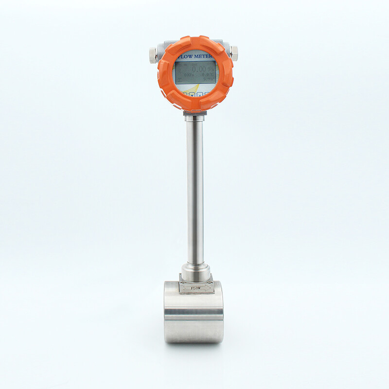
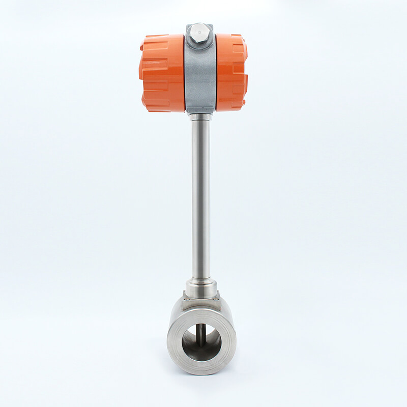
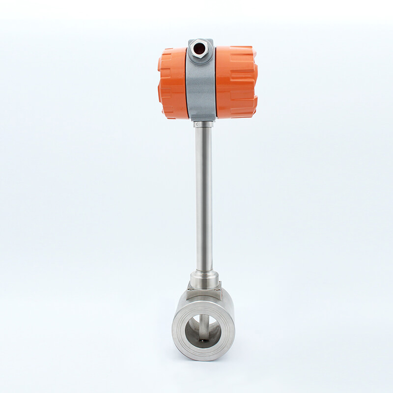
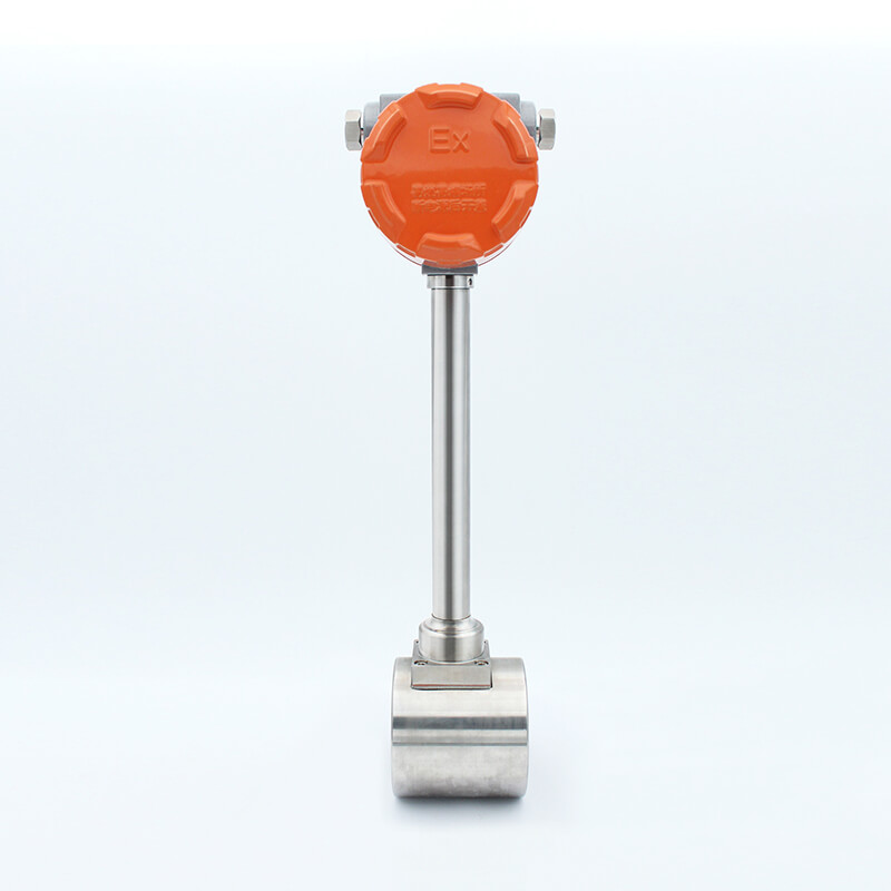
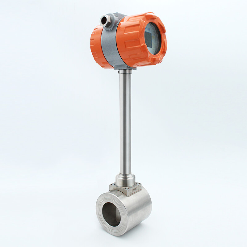
Standard vortex flowmeters are widely used in petroleum, chemical, metallurgy, electric power, textile, papermaking and other industrial fields to measure the volume flow of liquids, gases and steam. In the chemical and petrochemical industries, such as power generation and heating systems, its application involves a variety of different fluids: superheated steam, saturated steam, compressed air, oxygen, nitrogen, hydrogen, natural gas, coal gas, liquefied gas, flue gas, carbon dioxide, fully desalted water, solvents, thermal oil, boiler feed water, condensate, etc. Measurement and control of water and liquids, gasoline, alcohol, benzene, etc.
Advantages
Advantages and Disadvantages of Vortex Flowmeter
The vortex flowmeter body is durable and widely used for liquids, gases and steam, and is optimized for steam applications.
For gas measurement, if the gas temperature and pressure change greatly, pressure and temperature compensation must be performed, and the vortex flowmeter can add temperature and pressure compensation.
The vortex flowmeter adopts Japanese OVAL technology and design.
In order to protect the sensor, the vortex flowmeter adopts an embedded sensor, and 4 piezoelectric crystals are encapsulated inside the sensor, which is our patent.
The vortex flowmeter sensor has no moving parts, no wear, no vulnerable parts, and adopts a fully welded SS304 stainless steel body (SS316 stainless steel is optional).
The vortex flowmeter adopts a patented sensor and flow sensor body, which can greatly eliminate the influence of field drift and vibration compared with other flowmeters.
In addition to the electromagnetic flowmeter and ultrasonic flowmeter can be used as flowmeter and BTU meter, the vortex flowmeter can also be used as a BTU meter after adding a temperature sensor and accumulator to measure the energy of steam or hot water.
Ultra-low power consumption: 24 VDC, 15 watts maximum;
In gas measurement, vortex flowmeters can achieve high accuracy of ±0.75%~±1.0% of reading (±1.0% for gas and ±0.75% for liquid); can be used for custody transfer, while metal tube rotor flowmeters or orifice flowmeters are usually used for process control.
Vortex flowmeters offer a variety of signal outputs and options, such as 4-20mA, HART pulse or RS485 pulse.
Among electronic devices that measure flow, vortex flowmeters are the only ones that can withstand a wide temperature range (up to 350°C), while digital flowmeters can withstand the highest process temperatures.
Application
Vortex flow meter applications
Vortex flow meter is professional in measuring non-conductive liquids, gases, saturated and superheated steam, especially for steam measurement trade settlement.
Except work as flow meter, vortex flow meter can also work as heat meter to measure the Gross/net heat of steam and hot water.
Vortex flow meter usually monitor the compressor output and evaluation of Free Air Delivery (FAD)
There has lots of Industrial gases, such as natural gas, nitrogen gas, liquefied gases, flue gases, carbon dioxide etc, all could use vortex flow meter.
In many factories, compressed air monitoring is very important, vortex flow meter also could use for process control.
Besides the different gases measurement, vortex flow meter could also used for light oil or any purified water,such as thermal oils, Desalinated water, demineralized water, RO water, boiler feed water, condensate water etc.
In the Chemicals and petrochemicals industries, there also has lots of gases or liquid could use vortex flow meter for monitoring.
Technical Data
Table 1: Vortex Flow Meter Technical Data
|
Product Paramenters
|
||||
|
Protection Grade
|
IP65
|
|||
|
Applicable Medium
|
Liquids: water, high-temperature water, oil, food liquids, chemical liquids, etc.;
Gases: air, oxygen, nitrogen, coal gas, natural gas, chemical gases, etc.; Gas steam: saturated steam, superheated steam. |
|||
|
Measurement sensor
|
||||
|
Nominal Diameter
|
DN15-DN300 (300-1000 insert type)
|
|||
|
Range of
|
1:6-1:30
|
|||
|
Medium temperature
|
-40℃-250℃,-40℃-350℃
|
|||
|
Nominal pressure
|
≤1.6Mpa ≤ 2.5Mpa ≤ 4Mpa(Other pressure can be custom,need consult supplier)
|
|||
|
Output
|
Current (4-20 mA) , pulse , frequency , state switch
|
|||
|
Accuracy
|
Liquid 1.0%,Gases and Steam 1.5%
|
|||
|
Flow rate range
|
Liquids:0.27-9m/s,Gases:3-80m/s,Steam:3-90m/s
|
|||
|
Power
|
AC86~230V or DC24V(optional)
|
|||
|
Power Supply Voltage
|
3.6VBattery,+12V DC,+24DC
|
|||
|
Shielded cable
|
Signal section,wire: 0.5mm2 Cu /AWG20
|
|||
Table 2: Vortex Flow Meter Structure Drawing
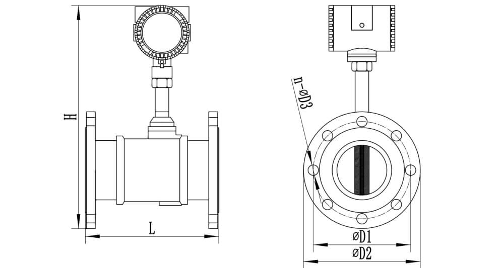
| Caliber(mm) | Inner Diameter d (mm) | Length L (mm) | Height H (mm) | Flange Outer Diameter D2(mm) | Central Dia of Bolts Hole D1(mm) | Bolt Hole Diameter D3(mm) | Screw Quantity n |
| 15 | 15 | 170 | 440 | 95 | 70 | 15 | 4 |
| 20 | 20 | 170 | 443 | 100 | 75 | 15 | 4 |
| 25 | 26 | 170 | 455 | 125 | 90 | 19 | 4 |
| 32 | 32 | 170 | 460 | 135 | 100 | 19 | 4 |
| 40 | 38 | 190 | 460 | 140 | 105 | 19 | 4 |
| 50 | 48 | 190 | 466 | 155 | 120 | 19 | 4 |
| 65 | 62 | 220 | 482 | 175 | 140 | 19 | 4 |
| 80 | 73 | 220 | 492 | 185 | 150 | 19 | 8 |
| 100 | 95 | 240 | 528 | 210 | 175 | 19 | 8 |
| 125 | 118 | 260 | 561 | 250 | 210 | 23 | 8 |
| 150 | 140 | 280 | 605 | 280 | 240 | 23 | 8 |
| 200 | 200 | 300 | 636 | 330 | 290 | 23 | 12 |
| 250 | 250 | 360 | 702 | 400 | 355 | 25 | 12 |
| 300 | 300 | 400 | 745 | 445 | 400 | 25 | 16 |
Table 3: Vortex Flow Meter Flow Range
| Size(mm) | Liquid(Reference medium:normal temperature water, m³/h) | Gas(Reference medium:20℃, 101325pa condition air, m³/h) | ||
| Standard | Extended | Standard | Extended | |
| 15 | 0.8~6 | 0.5~8 | 6~40 | 5~50 |
| 20 | 1~8 | 0.5~12 | 8~50 | 6~60 |
| 25 | 1.5~12 | 0.8~16 | 10~80 | 8~120 |
| 40 | 2.5~30 | 2~40 | 25~200 | 20~300 |
| 50 | 3~50 | 2.5~60 | 30~300 | 25~500 |
| 65 | 5~80 | 4~100 | 50~500 | 40~800 |
| 80 | 8~120 | 6~160 | 80~800 | 60~1200 |
| 100 | 12~200 | 8~250 | 120~1200 | 100~2000 |
| 125 | 20~300 | 12~400 | 160~1600 | 150~3000 |
| 150 | 30~400 | 18~600 | 250~2500 | 200~4000 |
| 200 | 50~800 | 30~1200 | 400~4000 | 350~8000 |
| 250 | 80~1200 | 40~1600 | 600~6000 | 500~12000 |
| 300 | 100~1600 | 60~2500 | 1000~10000 | 600~16000 |
| 400 | 200~3000 | 120~5000 | 1600~16000 | 1000~25000 |
| 500 | 300~5000 | 200~8000 | 2500~25000 | 1600~40000 |
| 600 | 500~8000 | 300~10000 | 4000~40000 | 2500~60000 |
Table 4: Vortex Flow Meter Model Selection
| LUGB-2 | x | x | x | x | x | x | x | x | x | x | x | ||
| Caliber | DN15-300mm/1/2"-12" | ||||||||||||
| Measured Medium | Saturated Steam | S | |||||||||||
| Superheated Steam | M | ||||||||||||
| Common Gas | C | ||||||||||||
| Liquid | L | ||||||||||||
| Others | O | ||||||||||||
| Nominal Pressure | 0.6MPa | 1 | |||||||||||
| 1.0MPa | 2 | ||||||||||||
| 1.6MPa | 3 | ||||||||||||
| 2.5MPa | 4 | ||||||||||||
| 4.0MPa | 5 | ||||||||||||
| Nominal Temperature | -40℃~250℃ | 2 | |||||||||||
| -40℃~350℃ | 3 | ||||||||||||
| Structure | Compact type | C | |||||||||||
| Remote type (converter display) | R1 | ||||||||||||
| Remote type (flow computer remote display) | R2 | ||||||||||||
| Connection | Flange(DN15-300mm) | PN10/PN16/PN25/PN40(DIN) | D** | ||||||||||
| A15:150#, A30:300# (ANSI) | A** | ||||||||||||
| 10K/20K/30K/40K (JIS) | J** | ||||||||||||
| Wafer(DN15-300mm) | W | ||||||||||||
| Thread(DN15-100mm) | T | ||||||||||||
| Insertion(DN80-2000mm) | I | ||||||||||||
| Body Material | SS304 (standard) | 4 | |||||||||||
| SS316 | 6 | ||||||||||||
| Compensation | Without | W0 | |||||||||||
| With temperature compensation | WT | ||||||||||||
| With pressure compensation | WP | ||||||||||||
| With temperature & pressure compensation | W2 | ||||||||||||
| Output | 4-20mA,pulse,RS485 | A | |||||||||||
| 4-20mA,pulse,HART (converter display only) | B | ||||||||||||
| Power Supply | DC24V | D | |||||||||||
| 3.6V Battery Powered (converter display only) | B | ||||||||||||
| AC220V (flow computer type only) | A | ||||||||||||
| Ex-Proof | Without | W | |||||||||||
| With (Exia ll CT5 Ga) | E | ||||||||||||
Installation
1.The electromagnetic flowmeter shall be installed atthe rising part of the pipeline.
2.The electromagnetic flowmeter shall be installed at the lower part andthe vertical upward part of the horizontalpipeline,and shall not be installed atthehighest point and the vertical downwardpart of the pipeline.
3.There shall be at least a straight pipe section with a length of 10 * D (D is theinner diameter of the flowmeter) in front of the flowmeter and a straight pipesection with a length of5 * D behind.
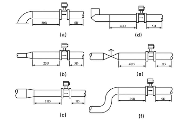
Vortex flowmeter is a flowmeter that is sensitive to pipeline velocity distribution distortion, rotational flow and flow pulsation. Therefore, full attention should be paid to on-site pipeline installation conditions and the requirements of the manufacturer's instruction manual should be followed,We will contact flow meter experts for guidance or installation.